What is VHDL?
I mentioned in my previous blog that I was writing VHDL code for a Xilinx FPGA! And by saying that, I assume you lost me completely =(.
So, let’s define the acronyms!
[[FPGA]]: Field Programmable Gate Array
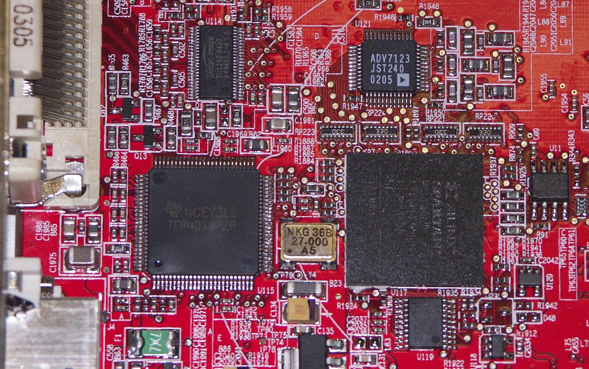
An FPGA is a customizeable piece computer chip. Usually when a chip performs a function, it is because it has little tiny circuits drawn out on its silicon. On a basic level, chips contain transistors which are combined in various ways to create gates, flip-flops, muxes, multipliers, counters, adders, and higher and higher level stuff until you get to things like memory and finally processors. In an FPGA, none of the connections between gates is set in stone. By writing code (see below) you can instruct the FPGA how to form the connections between various gates. An large enough FPGA can be made into virtually any other component (of course, with the complexities of processors these days, it would take years to program an FPGA). FPGAs can be commonly found in computers. Vendors often use them to perform special tasks. some leading manufactureres of FPGAs include Xilinx, Altera, and Lattice. Look in your computer for one of these chips! You can often find one on PCI cards, espcially ATI graphics cards, and sometimes on motherboards (look near the southbridge. It may even be the southbridge). they’re usually large, square chips without any evident pins. The chip on the right is a Xilinx FPGA.
[[VHDL]]: VHSIC Hardware Description Language (and VHSIC stands for Very High Speed Integrated Circuit, which is fancy for computer chip).
VHDL is a programming language often used to program FPGAs. It is unique in that the code itself is never run or compiled. The code is “synthesized,” or translated, into a description of how the FPGA should program itself. After the code is written, it is synthesized into a netlist of connections, which is then routed onto the FPGA, creating connections between various components to create larger units and eventually a fully functional chip. The code is quite weird, as instead of writing instructions on what you want a processor to do, you are establishing connections. Another thing, all the lines of code execute at the same time. There is no top-to-bottom order. A lot of activity occurs on “clocks”. Clocks are what control the speed. In my case, our Xilinx is running at 40 mhz (but theoretically can run over 2 ghz given the right oscillator). A 40 mhz clock “ticks” 40,000,000 times a second. That’s a lot of stuff that can happen all at once! In addition to running all at once, things often never stop!
Let’s do some example VHDL: (–is a comment)
entity sample is			--An Entity is a building block of VHDL

    port(				--This will list the ports described

	in signal A : std_logic;	--This creates "A" as a logical (1 or 0) input.

	in signal B : std_logic; 	--This creates "B" as a logical (1 or 0) input.

	out signal E : std_logic	--This creates "E" as a logical (1 or 0) output.

   );

end sample;				--End description of the entity

--Now, to describe what this entity actually does!

architecture synthesis of sample is	--Architecutres describes the function of an entity.

--These two signals are "interior" signals that are not connected outside the FPGA

signal C : std_logic;

signal D : std_logic;


begin

    C <= A AND B; 	--Perform a logical AND operation (if both are 1, C becomes 1)

"<=" is the assignment operator.

    D <= A OR B;	--Perform a logical OR operation (if either are 1, D becomes 1)

    E <= C AND D;	--Perform a logical AND operation (if both are 1, E becomes 1)

end synthesis
So what is the result? If I synthesize this (I just did), it first shows me something like this:
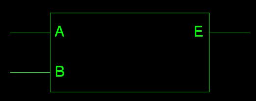
The inputs A and B are on the left, and the sole output E is on the right. But how does it do what it does? Double clicking gives a further look!
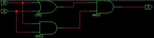
Here you can see the gates that it made. The AND gates have straight left lines, and the OR gate has curved lines.
You can pretend to trace a signal to see what will work and what won’t. I realize now this was pretty pointless, as it only operates as an AND gate =p
Here’s the truth table anyway
Signal A 0 1 0 1

Signal B 0 0 1 1

Signal E 0 0 0 1
So, VHDL is pretty practical, but its really a pain to program in, because I’m so used to C and other PC based programming languages and its hard to deal with clocks and the idea that everything happens at once. Oh, did I mention the only allowable type of number is binary? No integers =(.
July 18th, 2007 at 12:06 am
I’m glad i decided to check ur blog for once, I completely understand this stuff yay!!! ^_^ looks like fun lol
July 18th, 2007 at 12:13 am
Also what about Nands and nors
July 18th, 2007 at 12:22 am
Ur very picky with your comments lol
July 18th, 2007 at 12:27 am
You would not believe the amount of spam I get.
Nands and Nors? Simple, just add a not gate to the output!
It’ll even do XORs!
July 20th, 2007 at 11:29 am
I honestly couldn’t do coding, my mind just can’t grasp that idea.
But this did help me understand what you are doing… kinda.
Also helped the time pass at work.